Cave Generator Libray
One of the filters in the Visual Studio project is called Cave Generator. This applies to both the header files and the source files. The following files used in the DLL library for cave generation are listed below.
Header Files
- CaveGenerator.h
- MeshGenerator.h
- Room.h
- SquareGrid.h
- Utils.h
Source Files
- CaveGenerator.cpp
- CavePrinter.cpp
- MeshGenerator.cpp
- Room.cpp
- SquareGrid.cpp
All of these files can be viewed from the following link: View Source Folder
CaveGenerator
This is the main class that generates a random cave. After it has been instantiated, the GenerateMap() function generates the cave. It does this through the following steps:
- Generate random noise
- Smooth out the generated noise to create rooms
- Detect and Removing the isolated walls
- Detect and remove rooms that are below the treshhold
- Finding the two closest disconnected rooms and connect them
- Create passages between the rooms
- Add a border around the map to close off any rooms around the edge
- Create marching squares for the edge tiles
- Generate 3D mesh from the cave
Step 1 - Generating Random Noise
")
The step takes place by calling RandomFillMap(). A series of values set to either 1 or 0 are generated before being added to a 2D array of integers using a class called Array2D which is defined in the types.h header file. a 1 corresponds to a wall while a 0 is an open space
We start by iterating through every x and y coordinate in the map using nested for loops until the width and height have been reached. if the x or y coordinate is on the edge of map a 1 will always be generated. Otherwise a 1 or a 0 will be picked at random using the PsuedoRandom class.
Step 2 - Smooth Map
")
This step contains a process that is run through 5 iterations by calling the SmoothMap() function on each iteration. Through each call of smooth map we iterate through the every space on the map and check how many surrounding tiles are walls by calling GetSorroundingWallCount() where we loop through a 3x3 grid that includes the 8 sorrounding tiles. if the tile is set to 1 or it is outside of the map we increase the wall count.
Once we have the total number of neighbour walls if it is greater than 4 will set the current position to a 1 (wall) and if it is less than 4 we set it to a 0 (vacant space). If it is exactly 4 then the tile is left as to what it is currently set to. Once this process is complete we get start to get something the resembles a cave.
Step 3 - Find and Remove isolated walls
")
In this step we start by finding isolated wall regions using a function called GetAllRegions(). In this function we iterated through all tiles in the map checking if it is a wall tile. If it is then find out all of the wall tiles that are connected to it by calling the GetRegionCoords function.
GetRegionCoords() - Information coming soon.
Once all of the coordinates for that region have been returned they are then added to the isolated regions list and then all of the tile in that region are set to have being already checked.
Next for every isolated wall region we check how many tiles are in it and compare it to the wall threshold. If it is below the threshold then we set every tile in that region to zero making it a vacant space.
Step 4 - Detect and remove rooms that are below the treshhold
")
In this step we start by finding all room regions. This is done the exact same way as the previous step except we pass a zero to the GetAllRegions() function instead of a 1 so that it searched for vacant spaces. Once the room sections have been returned we then iterate through them. If the number of tiles in a room is less the the room threshold size then we set each of the tiles in the room to a 1 to remove it. If it is not below the threshold the room is then added to the rooms list by creating a new room object which includes the edge tiles.
Once all remaining rooms have been added to the list they then get sorted from largest to smallest with the largest being set as the main room.
Step 5 - Finding the two closest disconnected rooms and connect them
")
This step is performed by calling a function called ConnectClosestRooms recursively. Within this function a series of sub steps are performed.
First we determine whether to force access from the main room (largest one). If we iterate through all rooms setting them to be connected to this one. Otherwise we add all rooms to the connected and disconnected lists. Next we iterate through every room the connected rooms list (Room A). For evert connected room we then iterate through every disconnected one. We then iterate through every tile that is on the edge on room A and every tile that is on the edge of room B. We then check the distances between point A and point B using Pythagoras theorem of c^2 = a^2 + b^2.
If the distance between room A and room B is shorter than the shortest distance or we do not have a shortest yet then it becomes the new shortest distance and we set the two point and the two rooms to be the closest. Next if a connection was found and we a forcing a connection from the main room we then create passage between the closest rooms by calling create passage. We then run another iteration of this function.
This process will repeat until there all rooms have been iterated through. Then if we were not forcing access from the main room we call the function again with "force access" turned on. Once this finishes the main room will have a path to all other rooms.
Step 6 - Create passages between the rooms
")
In this step we use the CreatePassage function which first calls ConnectRoom on the room class to set room a and room b to be connected to each other. Next we create a path between the two edge tiles by calculating a line using the CreateLine function.
This function gets the difference in x between the two points and the difference in y between the two points. It then takes the adds a series of steps along the gradient of the line, adding the coordinate of each step to the line coordinate vector which is then returned as the path.
[Insert additional information]
Once the path has been created we then carve a circle at each point in the path so that a corridor has been carved between the two rooms. The CreateCircle function does this by first taking the "passage width" as a radius. We then iterate through every x and y value within that radius and use Pythagoras theorem to check if we are inside by comparing it to the radius (x * x + y * y <= radius * radius)
if the coordinate is inside the circle and not outside the bound of the map then the tile is set to 0 to make it a vacant space.
Step 7 - Add a border around the cave
In this step we make the walls around the edge of the cave thicker. We do this by creating a new 2D array which is equal to the width and height of the map plus 2*the border size. We then iterate through each index in the bordered map array setting the value to 1 if we are outside the width and height to create a new wall. If we are inside the borders then we retrieve the value from the old 2D map array and set it by subtracting the border size from the x and y value.
This becomes the new map that we use to generate the marching squares and the 3D mesh.
SquareGrid
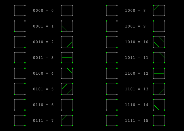
This is the class used to perform Step 8 - Create marching square configurations. It create a 2D array of marching squares and returns it as a square grid. marching squares are tiles that have a polygon inside them connecting a series of nodes. These are used to define the type of graphic that should appear for each edge tile rather than making them all full squares. Each square has 4 corner nodes. The shape that gets drawn depends on which of these nodes are turned on or off. Each of the corner nodes store a 1 if it is turned on and a 0 if it is turned off this produces a 4 digit binary number between 0 and 15. So there are 16 different configurations in total for the marching square from 0000 to 1111. Each of these configurations are shown in the image below.
The square grid class uses 3 different structs defined in the header file: Square which is one marching square on the grid, Node which is a node on the square, and ControlNode which is extends Node and is one of the nodes in the corner that can be turned on or off. In this program we also have 4 other nodes halfway along the each edge of the square (top, right, bottom and left). These ones determine where each line starts and finishes.
When the SquareGrid class is Instantiated the the constructor firstly creates a 2D array of control nodes. Next we iterate through each tile in the map and calculate the coordinate of the top left control node base on the size or each square. We then create a new control node at that position and add it to the control nodes array. If the tile is a wall then the control node is set to on otherwise it is off. Each control node also has a reference to the node that is above it and one to the right of it.
Next a 2D array of the Square struct is created. For each tile in the grid a new square is then created with the position of the 4 control nodes assigned to it ( top left, top right, bottom right, bottom left). The edge nodes are then assigned to the control nodes. The next step is to set the configuration of the marching square. This is done by setting a configuration variable to 0 and then adding to it depending on which control nodes are active. The top left is the first bit, top right is the second bit, bottom right is the third bit and bottom left is the fourth bit.
Once the configuration has been defined the square is then added to the squares 2D array before moving to the next position.
There is also a function called triangulate square which assigns each of the edge nodes that are to be used to a list in the Square struct by checking the configuration of the square.
MeshGenerator (Not currently working)
This class is used for step 9 - Generate 3D mesh from cave.
Information on this is coming soon.
Linkage
The linkage.cpp file contains all of the external functions that are compiled into the DLL to be used by other programs. The following functions are used for the cave generator.
GenerateCave -This is the function that gets the library to generate a new random cave using all of the customizable parameters. After instantiating a new cave generator as a pointer and generating the map it returns the object.
IsWall - Checks if the value at a specified x and y position is a 1 and if it returns true. Otherwise, it returns 0.
GetMarchingSquareValue - Retrieves the marching square configuration at a specified x and y position and returns it as an integer.
GetSeedValue - Returns the random seed number generated by the cave generator
DeleteCavePointer - deletes the current CaveGenerator game object from the heap to prevent memory leaks and make room in memory for a new one to be created.
Dungeon Generator Unity Application
")
Information on this is coming soon.
CaveGenerator
This is the main class that reads from the DLL file after being imported into Unity. It contains a whole range DLL imports including the matching functions for GenerateCave, IsWall, GetMarchingSquareValue and GetSeedValue.
When the class is instantiated using the CaveGenerator constructor, we create an integer pointer that receives the value from GenerateCave. A 2d boolean array is then initialized for the map followed by a 2D byte array for the marching squares. A public integer is then used to store the seed. Next, we iterate through the map array calling IsWall on each x/y coordinate to check if there is a wall there and assign true or false accordingly. We then iterate through the marching squares array calling GetMarchingSquareValue on each x/y coordinate to get the marching square configuration. Both of the 2D arrays are public, allowing access from other classes.
MapGenrator
This is the Unity class that contains an instance of the CaveGenerator class which generates the cave through the DLL. As soon the scene loads or the left mouse button is clicked GenerateMap() is invoked which instantiates the cave using the CaveGenerator constructor where it passes in all of the map properties assigned on the component shown on the right. It then generates the 3D mesh from the marching squares in the cave using the MeshGenerator class.
There are also functions that let you print the cave or marching square values from the DLL to the Unity console.

MeshGeneratorNew

This script is used to generate the 3D mesh that makes the cave appear on the screen once it has been generated. There are public variables that let you adjust the height of the wall as well as the tiling of the texture.
When GenerateMesh is invoked we initialize a 2D array of the Square class for the marching square. We then iterate through each position instantiating a new square and then invoke TriangulateSquare which creates the vertices needed to build each triangle for the part of the 3D mesh.
We then use Unity's Mesh class to create a new mesh. The vertices and triangles are then assigned to the mesh using lists that were created earlier. After the normals have been recalculated the mesh is then assigned to a mesh filter. The uvs for the texture are then assigned using an array of 2D vectors that have calculations made to it using the marching squares. The mesh for the wall is then generated by invoking GenerateWallMesh()
More information coming soon.
CaveUIManager
This is the script that allows the user the generate a cave from the in-application user interface. It takes all of the components for the slider controls, toggles and the text that updates from the slider values. The mesh generator, camera and input manager game objects are also assigned to this script.
As soon as one of the values from a slider is updated, a Unity event invokes one of the public functions defined in this file. Each of these functions sets the value of a private variable which is passed as one of the parameters when the cave is generated. If there is already a cave in the scene it will also invoke Regenerate to update the output of the cave immediately.
When the Generate cave button is clicked, the GenerateCave() function is invoked which calls the CaveGenertor class that uses the DLL.
